-Smart surface
-Holds
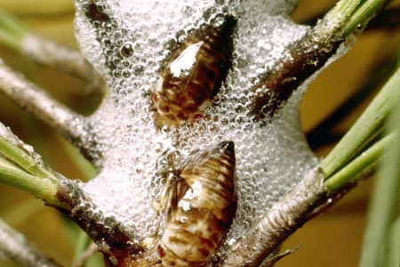
-Optimally packed spheres (with inspiration from the spittle bug http://www.organicgardeninfo.com/images/spittlebugs.jpg)
Initially, the ideas consisted of a structure that was filled with spheres packed in the fcc orientation. The design consisted of chipboard walls with holes cut into them to allow small spheres (ping-pong ball size) to fill it without gaps on the sides.
Figure 1 is a model made in Rhinoceros that shows how the spheres would protrude from the holes cut into the chipboard. In this design, the chipboard structure optimally holds the spheres.

Figure 1
Figure 2 is a model made in Rhinoceros of the second initial design. It is similar to the one shown in Figure 1 except that there is also a structure on the inside and the spheres fill the area between the two panels of chipboard. Initially, it was thought this was the better of the two as it holds the spheres optimally and can hold something else in the inner compartment.

Figure 2
After a night it was agreed upon by the group that we had left out the 'smart' portion of our surface. The definition of 'smart' was discussed in depth and it was decided that the surface had to respond to or interact with something.
Again, two ideas were purposed. One of which was a ramp and basket combination that spheres would roll down and end up in the fcc orientation. The other was a structure consisting of stacked spheres (in fcc orientation) that opened to hold something. Figure 3 is a preliminary sketch of this design. The spheres would be made of leaf-like panels that would open by means of rotating around an axis.

Figure 3
The group split into two in order to more efficiently pursue both design concepts. It was decided that each sphere in the structure should be aprox. 6 inches in diameter and be composed of a rigid hemisphere that was connected to 6 freely moving leafs that would overlap each other. Figure 4 is a model made in Rhinoceros that shows the hemisphere (front of figure) and overlapping panels (back of figure).

Figure 4
Three chipboard models were made of this design; The second of which was improved to make the final structure more spherical and the third to allow for a better connection between the hemisphere and the panels. Figure 5 shows the first two spheres and Figure 6 shows the third.

Figure 5

Figure 6
There were a few rotation problems with the front panels, so a modification that was two hemispheres (similar to the current back) one of which slightly smaller than the other that rotate into each other was purposed. One sphere made with the previously mentioned two hemisphere method and it rotated much better.
The group met as a whole and it was determined that we would all proceed together with the stacked spheres. Gluing the panels, instead of tape, was purposed and found to make the spheres rotate past each other without catching as much. This resulted in making two more spheres were with glue and remaking the original two hemisphere sphere with glue.
No comments:
Post a Comment